TAP, DAP, AP, and Device Connectivity
Preface
Modern ARM-based SoCs expose powerful debug and trace capabilities through a layered architecture defined by IEEE 1149.1 (JTAG) and ARM CoreSight.
This article explains, step by step, how TAP, DAP, AP, and debuggable devices connect together, and how tools like OpenOCD and J-Link interact with them.
1. High-Level Debug Stack Overview
At a conceptual level, ARM debug access follows this hierarchy:
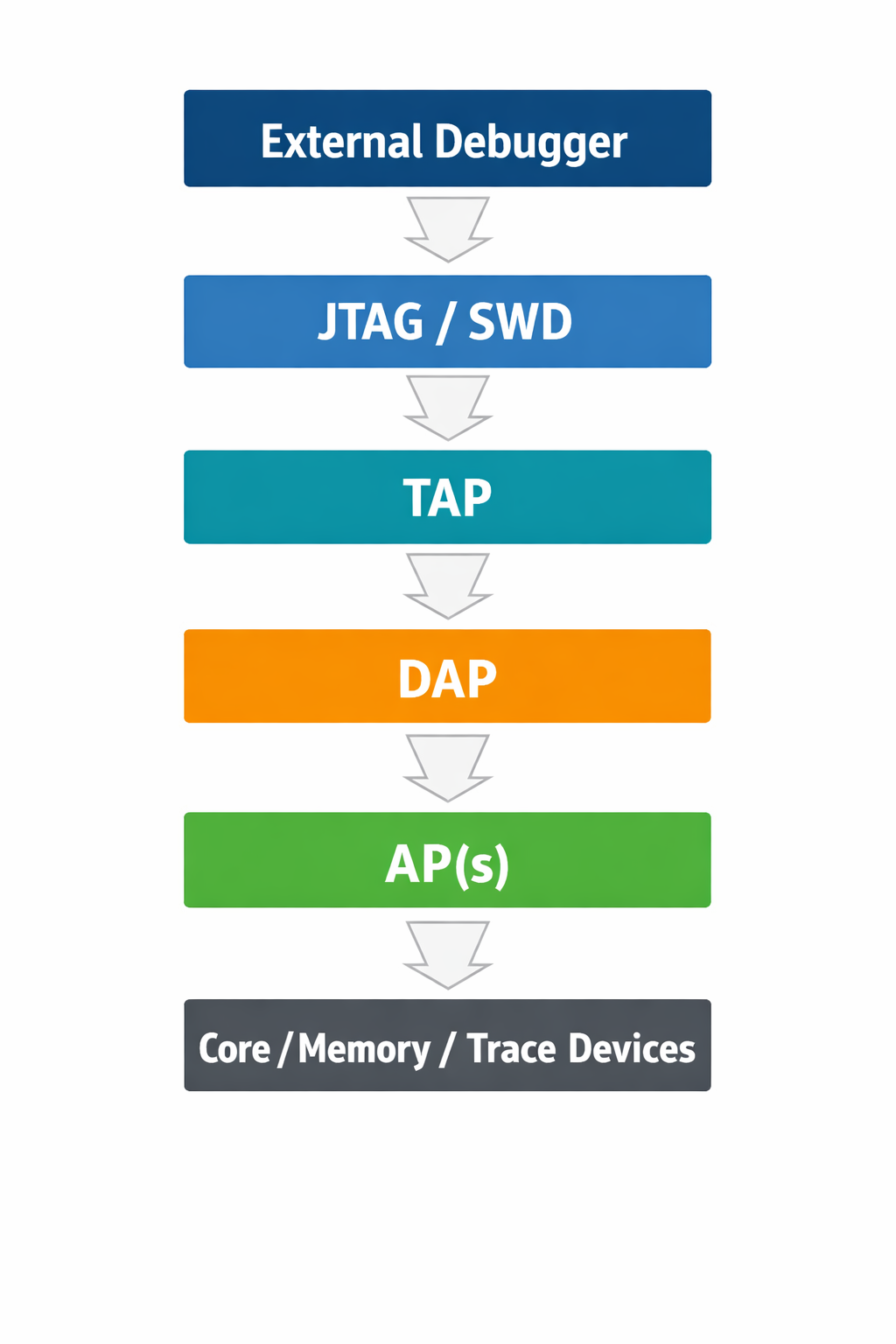
Each layer has a well-defined responsibility and strict access rules, especially on secure SoCs.
2. TAP – Test Access Port
2.1 What is a TAP?
The Test Access Port (TAP) is defined by IEEE 1149.1 (JTAG).
It is the physical and logical entry point into the chip’s test and debug logic.
2.2 TAP Signals
| Signal | Description |
|---|---|
| TCK | Test clock |
| TMS | Test mode select |
| TDI | Test data in |
| TDO | Test data out |
| TRST (optional) | TAP reset |
2.3 TAP Responsibilities
- Implements the JTAG state machine
- Shifts instructions into the Instruction Register (IR)
- Shifts data through the Data Register (DR)
- Exposes one or more internal scan chains
In ARM SoCs, the TAP typically exposes only one meaningful data path: the Debug Port (DP).
3. DAP – Debug Access Port
3.1 What is a DAP?
The Debug Access Port (DAP) is an ARM CoreSight component that bridges:
- JTAG or SWD
- To the internal CoreSight debug infrastructure
It is defined by ARM ADIv5 / ADIv6.
The DAP is not a core and not memory.
It is a router and protocol translator.
3.2 JTAG-DAP vs SWD-DAP
| Transport | Used when |
|---|---|
| JTAG-DAP | Multi-core, complex SoCs |
| SWD-DAP | Microcontrollers, Cortex-M |
Internally, both expose the same AP interface.
3.3 DAP Components
The DAP consists of:
- DP (Debug Port) – the externally visible port
- AP bus – internal bus to Access Ports
When a debugger reports that a DAP is detected, it means the transport layer is operational, but access to internal resources still depends on AP availability and security policy.
4. AP – Access Port
4.1 What is an AP?
An Access Port (AP) is a functional endpoint behind the DAP.
Each AP provides access to one class of resource.
4.2 Common AP Types
| AP Type | Purpose |
|---|---|
| MEM-AP | Access system memory and peripherals |
| APB-AP | Access CoreSight registers |
| JTAG-AP | Bridge to another JTAG domain |
| AXI-AP | High-performance system access |
Each AP has:
- An AP number (APSEL)
- Its own identification registers
- Independent access control rules
4.3 Why APs Matter
DAP access can succeed while AP access fails due to:
- Security restrictions
- Lifecycle state
- Incorrect AP numbering
- Power or clock gating
This often results in debug faults even though JTAG appears functional.
5. Devices Behind APs
5.1 What Are “Devices”?
Devices are the actual debug targets, such as:
- CPU cores (e.g., Cortex-A55, Cortex-M52)
- System memory
- Trace units (ETM, ETR)
- Cross-trigger interfaces (CTI)
These devices are never directly visible on JTAG.
5.2 Example Device Mapping
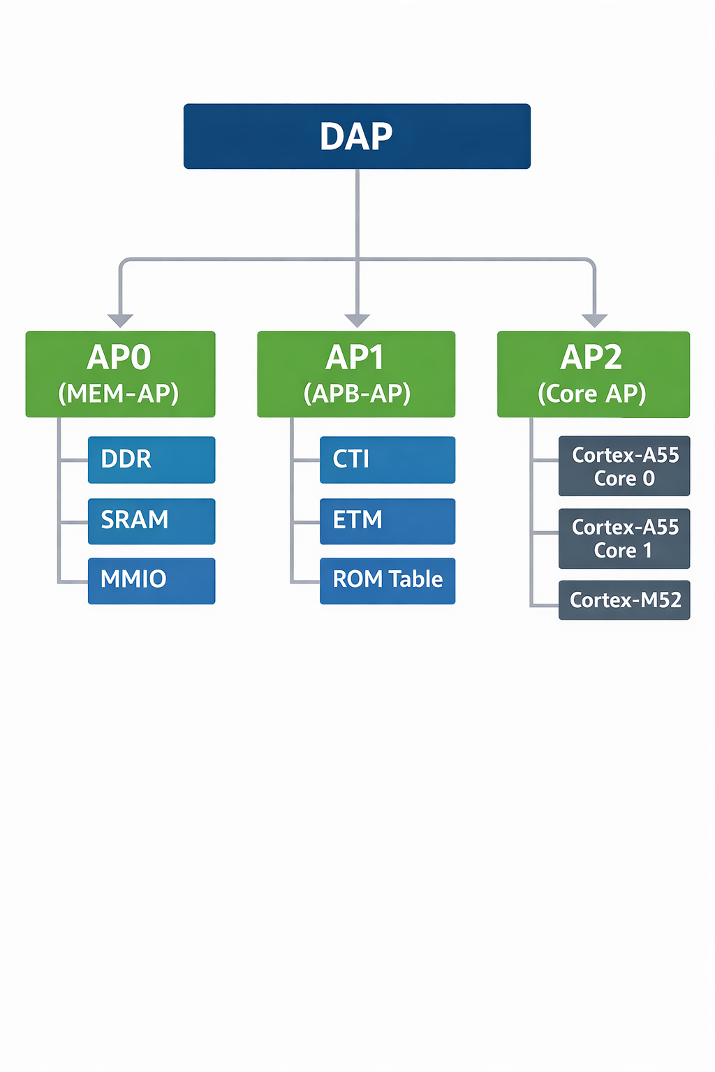
Each core has its own:
- Debug registers
- Power domain
- Security policy
6. Security and Lifecycle Effects
On modern SoCs, debug visibility is strongly influenced by security state and lifecycle configuration.
Typical behavior:
| Layer | Common State |
|---|---|
| TAP | Enabled |
| DP | Readable |
| AP | Conditionally locked |
| Core debug | Restricted or disabled |
This design ensures that invasive debug is only available when explicitly permitted by platform policy.
7. Key Takeaways
- TAP controls the physical debug transport
- DAP routes debug transactions internally
- APs expose specific classes of resources
- Devices are accessed only through APs
- Debug failures often indicate policy or lifecycle restrictions, not signal issues
Final Thought
Understanding the layered nature of TAP → DAP → AP → Devices is the key to debugging modern ARM SoCs efficiently. Once this mental model is clear, logs from Debug tool(like OpenOCD) stop being cryptic and start telling you exactly where access is being blocked.